Dental Implant Instruments

Universal Implant Surgical Kit

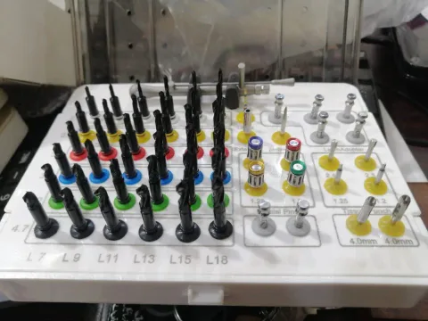
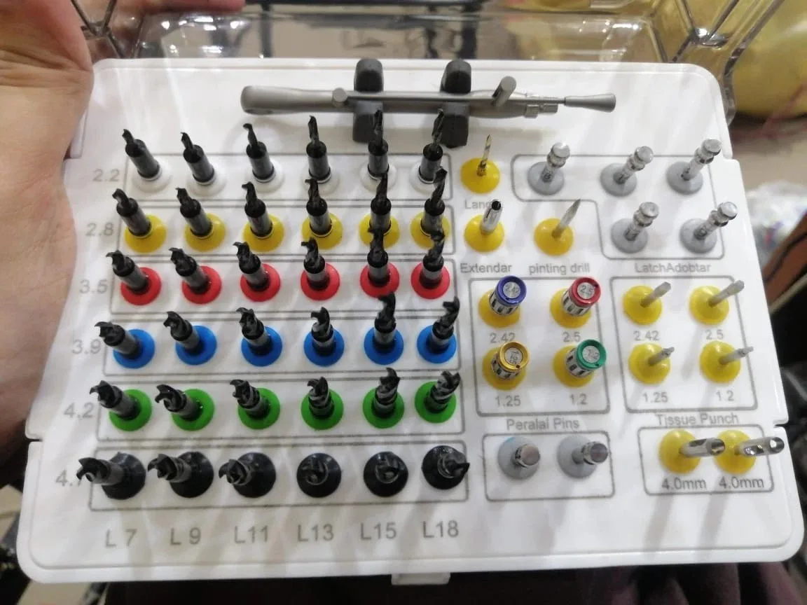
Implant surgical assortment with 36 drills marked L7 to L18 in a six-by-six layout, plus driver and extender, pins, two 4.0 mm punches, colour-coded cylindrical accessories and a wrench.

Listed pricing
Set $273.95Set $178.07Black Friday 202635% OFFYou save: Set $95.88Offer ends in12days08hrs46min53sec35% off all dental and surgical instruments, including listed and quoted product prices. No code needed. Shipping and taxes are separate.
In stock. Final price depends on the selected configuration and order requirements.
Product code
DIS-DEN-0382
MOQ
confirmed with your quote

Courier delivery. We ship through DHL, FedEx or another available courier, depending on your destination. We confirm the courier, shipping cost and estimated delivery time with your order. Shipping details

About Universal Implant Surgical Kit

The Universal Implant Surgical Kit contains 36 black drills in a six-by-six layout plus the accessories listed below. The drills carry length labels L7, L9, L11, L13, L15 and L18. Include your implant system and any guide system in your quote request so we can check fit.

Inside the kit

  • 36 black drills in a six-by-six layout, labelled L7, L9, L11, L13, L15 and L18
  • Driver and extender
  • Pins
  • Two punches, each marked 4.0 mm
  • Colour-coded cylindrical accessories
  • Wrench

The tray photo shows five pieces in the latch-adapter area, two in the parallel-pin area and four colored cylinders. The two punch seats are each marked 4.0 mm. Ask for the full counted packing list if your order specifies individual accessories.

If your order calls for drills and a holder, compare the separate 8-piece depth-marked drill option, DIS-IMP-SDR-GRP-8PC. Its listed drill sizes are 2.0, 2.5, 2.8, 3.2, 3.65, 4.2, 4.8 and 5.2 mm.

Planning guided cases

Fully guided surgery requires the drills, guide sleeves or keys, stop geometry and planning offset to be designed to work together. Their dimensions and contact relationships are system-specific. A surgical guide is produced for an individual case from the implant plan. If you intend to use this kit through a guide, send us the guide system, sleeve diameters and offset you plan with. We will check the kit against them before quoting.

Building your quotation

A useful enquiry for this kit covers:

  • Number of kits
  • The implant system and, if relevant, the guide system you use
  • The drill lengths and punch size your cases call for
  • Packing and documentation requirements

List your implant and guide systems in your quote request, or compare other assortments in our dental implant instruments range.
Locate a drill or part in the tray

Use the printed tray labels to point to one exact drill, or name the group a part belongs to, when you check the kit or ask about a replacement.

Read a drill position in the six-by-six grid

Each of the 36 drills sits where a printed row label meets a printed L column. The six L columns, L7, L9, L11, L13, L15 and L18, are printed along the bottom of the grid. Each of the six rows has its own printed label beside coloured holders. The table lists the rows from top to bottom.

Give a position as the row label plus the L column, for example row 3.5 (red holders), column L11. That points to one drill in the pictured tray. The row numbers are the labels printed on the tray, not dimensions we have measured. The grid helps you find a drill and does not set a drilling sequence.

Grid rows, top to bottom
RowPrinted labelHolder colour
1 (top)2.2White
22.8Yellow
33.5Red
43.9Blue
54.2Green
6 (bottom)4.7Black
Open implant kit tray with a six-by-six grid of black drills, columns labelled L7 to L18 and rows labelled 2.2 to 4.7, a wrench behind the grid, accessory groups at right and two 4.0 mm punches at lower right

Open tray, view 6. The drill grid is on the left and the separate component groups are on the right.

  1. Drill grid

    36 black drills, left side

  2. Row labels

    2.2 to 4.7, printed beside the coloured holders

  3. L columns

    L7 to L18, printed along the bottom

  4. Wrench

    Long wrench lying behind the grid

  5. Accessory groups

    Two groups of four at the right, one with colored tops and one with silver pieces in yellow holders

  6. Punches

    Two punches marked 4.0 mm, lower right

Name the group, then send the position

The two groups of four on the right share the printed tray labels 2.42, 2.5, 1.25 and 1.2. To identify a part, give the group and label and mark its position in the photo.

How to identify each group in a request
GroupWhat to state
Drill (36 in the grid)Printed row label and L column
Lance, extender or pointing drillName the position and send a marked photo
Latch-adapter areaMark which of the five tray positions you mean
PinsQuantity and a marked photo
Colored-top cylindersTray label and top color (blue, red, gold or green)
Silver pieces in yellow holdersTray label in the yellow-holder group
Punch4.0 mm punch and quantity
WrenchWrench and quantity
  1. Identify the kit

    Universal Implant Surgical Kit, SKU DIS-DEN-0382.

  2. Give the position

    For example: 1 drill, row 3.5 (red holders), column L11.

  3. Add your systems

    Name your implant system, and your guide system if you use one, so we can check the part against them.

  4. Attach the photo

    Circle the position on a copy of this tray photo.

Have experience with Universal Implant Surgical Kit?Share verified buyer or evaluator feedback. It takes about a minute.

Universal Implant Surgical Kit Questions

Is this kit a fully guided system or an instrument assortment?

It is offered as a drill-and-accessory assortment. It is not presented as a confirmed fully guided system. Guided use depends on the drills, guide sleeves or keys, stops and planning offset being made for one another. Send your guide system, sleeve diameters and offset convention with your enquiry, and we will check the kit against them before quoting.

What is a surgical guide, and is one supplied with this kit?

A surgical guide is a template produced for an individual case from the implant plan. It positions the drills during site preparation. A guide is not among this kit's listed components. The kit supplies drills, a driver and extender, pins, punches, colour-coded cylindrical accessories and a wrench.

How many drills are included, and how are they labelled?

The kit holds 36 black drills in a six-by-six layout with printed length labels L7, L9, L11, L13, L15 and L18. Manufacturers measure drill length differently, so compare the L labels with the length convention of your planning system and your drilling protocol.

What is the total piece count of the kit?

We describe this kit by its component groups: 36 drills, a driver and extender, pins, two punches marked 4.0 mm, colour-coded cylindrical accessories and a wrench. If your purchasing or tender process requires a total piece count, include that requirement in your quote request.

What has to match between the drill, the guide sleeve and the planned depth?

Check the drill's clearance in the sleeve or key, the stop's contact relationship, and the sleeve offset used in planning. Those measurements must agree with the guide system and implant system's drilling protocol; no single set of dimensions applies across systems. Send the exact guide-system specification with your enquiry.

WhatsApp

Black Friday

35%off

Save on everything from extraction forceps to orthodontic pliers and implant kits.

Offer ends in12days08hrs46min53sec

Browse the sale
A dental mirror, curved hand instruments and forceps arranged on a metal tray